What we read in and read out when transforming a program.
What kind of properties make a good representation?
This lecture explores different representations and their implications.
Code
from graphviz import Digraphimport astimport os def cmd(x): os.system(x)def ast_syntax(line):return ast.dump(ast.parse(line).body[0], indent=4)# Define a function to recursively add nodes to the Digraphdef add_node(dot, node, parent=None): node_name =str(node.__class__.__name__) dot.node(str(id(node)), node_name)if parent: dot.edge(str(id(parent)), str(id(node)))for child in ast.iter_child_nodes(node): add_node(dot, child, node)# Add nodes to the Digraphdef graph(line): dot = Digraph() add_node(dot, ast.parse(line).body[0])return dot
Concrete Syntax
Concrete syntax, or surface syntax, represents programs as they are written
Programs are text or surface syntax- just what you would type into an editor.
value = 8
result = 1
for i in range(value):
  result = result + i
print(result)
What is good and what is bad about this representation?
What is the level of abstraction?
How do you understand the semantics.
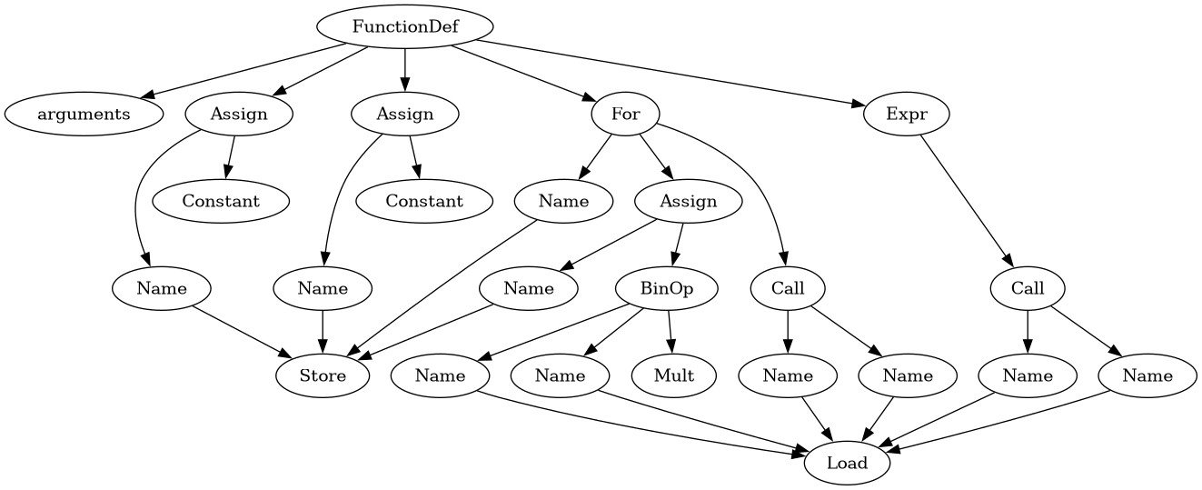
Abstract syntax
Abstract syntax represents programs as tree structures, focusing on the nodes and their connections.
Nodes are parts of the program,
Edges show how they are connected.
We can write this as a list or a graph
def pgm():
    value = 8
    result = 1
    for i in range(value):
        result = result * i
    print(result)
AST tree representation
An AST is a tree structure, nodes like ‘if’, ‘test’, ‘body’, assign’.
Each node is one concept from the program
Recursive function can walk over the tree, one chunk of code for each node.
Good - each type of node is different, making special cases are easy
Bad - each type of node is different so analysis has to know about every type, making general cases hard
This is the classic way to write an interpreter.
Simple (non optimizing) compilers often use this format.
A more regular representation
Programs are lists of instructions. Like an assembly instructions. Same sort of representation as LLVM.
ts2bril images/toy.ts | bril2txt
    //typescript program
    let value = 8
    let result = 1
    for (let i = 0; i < value;
         i = i+1)
    {
        result = result * i
    }
    console.log(result)
@main {
  v0: float = const 8;
  value: float = id v0;
  v1: float = const 1;
  result: float = id v1;
  v3: float = const 0;
  i: float = id v3;
.for.cond.2:
  v4: float = id i;
  v5: float = id value;
  v6: bool = flt v4 v5;
  br v6 .for.body.2 .for.end.2;
.for.body.2:
  v7: float = id result;
  v8: float = id i;
  v9: float = fmul v7 v8;
  result: float = id v9;
  v10: float = id i;
  v11: float = const 1;
  v12: float = fadd v10 v11;
  i: float = id v12;
  jmp .for.cond.2;
.for.end.2:
  v13: float = id result;
  print v13;
  v14: int = const 0;
}
bril
Looks like assembly
no limit on registers,
no condition codes.
fully typed,
no complex addressing modes.
easy to extend
Bril syntax
Declare functions, labels, instructions
instruction:
variable type = opcode arguments
opcode list of arguments
Form 1, variable is the destination, like a: int = add b, c
Form 2, no destination, like print a
what is good and what is about this representation?
    @main {
        v: int = const 4;
        jmp  .somewhere;
        v: int = const 2;
        .somewhere;
        print v;
    }
Code
%%{init: {"flowchart": {"htmlLabels": false}} }%%%%| fig-width: 6.5flowchart LR A[const 4] --> B[jmp] B --> C[print] D[const 2] --> C
%%{init: {"flowchart": {"htmlLabels": false}} }%%

%%| fig-width: 6.5
flowchart LR
  A[const 4] --> B[jmp]
  B --> C[print]
  D[const 2] --> C
notice label does not produce a node
Easy to see a dead instruction.
Third example:
    @main {
        v: int = const 4;
        b: bool = const false;
        br b .there .here;
    .here:
        v: int = const 2;
    .there;
        print v;
    }
Code
%%{init: {"flowchart": {"htmlLabels": false}} }%%%%| fig-width: 6.5flowchart LR A[v: int const 4] --> B[b: bool const false] B --> C[br b .there, .false] C --> D[v: const 2] C --> E[print v] D --> E
%%{init: {"flowchart": {"htmlLabels": false}} }%%

%%| fig-width: 6.5
flowchart LR
  A[v: int const 4] --> B[b: bool const false]
  B --> C[br b .there, .false]
  C --> D[v: const 2]
  C --> E[print v]
  D --> E
which is the true edge and which is the false edge , could mark the edges or use a convention
Which is the entry, which is the exit?
There is a long chain of instructions entered at the top, exit at the bottom, no branches inside.
CFG (cfg form 2)
nodes ares sequences of instructions.
jumps and branches can only be at the end of a sequence
only label has to be at the start
every instruction in the sequence executes the same number of times
construct cfg
walk over the instructions:
As we construct basic blocks, we can add instructions up till something that ends the block (terminator)
Option: do all blocks end in a terminator or not?
given a block b, the predecessors of \(b\) are the blocks \(b_{in}\) where there is an edge \(b_{in}->b\). And the successors of \(b\) are the \(b_{out}\) where \(b->b_{out}\) is an edge.
What is an algorithm that forms a cfg
just find all the basic blocks
add the control flow edges
pseudo code to construct cfg
in: instructions - list of instructions
out blocks - list of lists of instructions
current_block = []
for i in instructions:
    if i is not a label:
       block.append(i)
    if i is a label or terminator:
        blocks.append(current_block)
        current_block = []
step 2 we need a map from labels to basic blocks
in: instructions - list of instructions
out blocks - list of lists of instructions
current_block = []
for i in instructions:
    if i is not a label:
       block.append(i)
    if i is a label or terminator:
        blocks.append(current_block)
        current_block = []


for block in blocks:
   last = block[-1]
   if last is a jmp (one successor)
      add edge from block to last.dest
   else if last is a br (two successors)
      add two edges from block to last.true, last.false
   else  fall through
      add edge to next block (if it exists)